For a while I've wanted to build a 12″ rack panel to split the audio output from my laptop to go to (1) the amplifier that's on a shelf in my 'rig' (a stack of 13½″ wide x 9″ deep boxes), and (2) an FM transmitter, which broadcasts my music through the house (and the yard). I could just buy another headphone splitter (along with the requisite inline isolators and 1/4″ to 3.5mm adapters), but ever since I verified that amplifiers' line input is a high-impedance interface and therefore should be easily splittable to multiple devices I've wanted to build by own Y-splitter, but with built-in isolators, because I've some had bad luck with ground loops in the past and default to always isolating, now.
Design
Since I wasn't really sure whether I'd need isolators or not, I decided I had to make the whole thing super duper modular. The main panel would be a 12″ x 1½″ board, maybe 3⁄8″ thick. Each jack would get its own 1½″ sub-panel, as would each pair of isolators. To make the layout of the isolators simple, and to allow sub-panels to connect by stacking, left, common, and right would connect through #6 screws in the top, middle, and bottom holes along the edges, respectively, and a screw in the center of the top would be connected to the microphone pin. I don't don't plan to use that microphone conductor for anything, but included it on the panels for completeness.

Wire colors
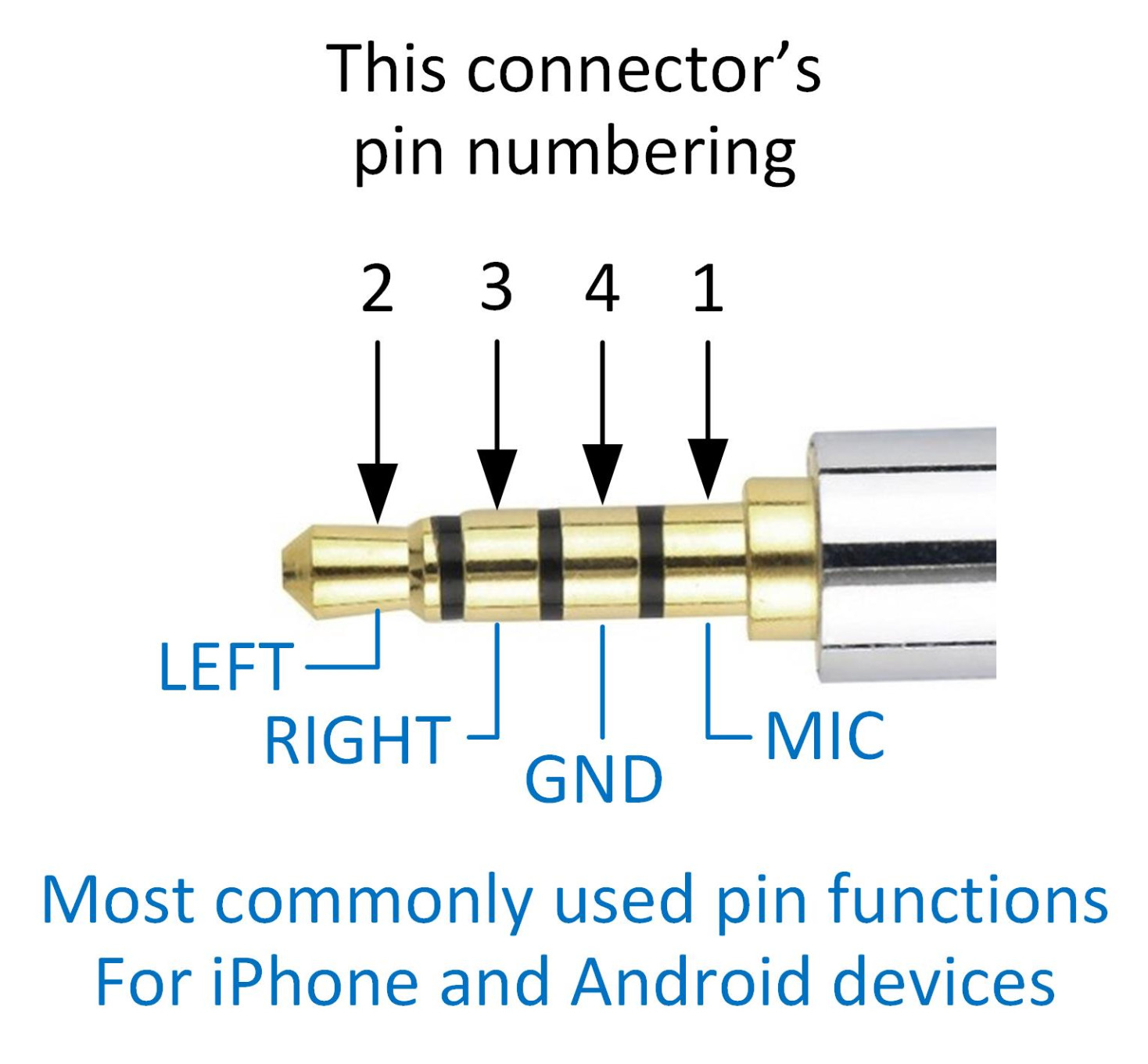
Following the CTIA standard and this lovely pin guide by Mike G (comment), which I verified with a cable and a multimeter:
| Color | Purpose | Position on panel | TRRS position | Jack pin |
|---|---|---|---|---|
| ▉ Yellow | Mic or vidio | Top middle | Sleeve | 1 |
| ▉ White | Left | Top | Tip | 2 |
| ▉ Red | Right | Bottom | Ring 1 | 3 |
| ▉ Black | Ground | Middle | Ring 2 | 4 |
Parts
- Wood from the abandoned wood pile
- Boiled linseed oil
- 3.5mm TRRS jacks
- isolation transformers
- A bunch of #6 nuts, bolts (1½″), and washers
- A bunch of #6 ring terminals
- Wires (20 AWG, I think), solder
Tools
- Table saw
- Mitre saw
- Belt sander
- Drill press with ⅛″, 5⁄32″, 5⁄16″, and ½″ bits
- Soldering iron
- Wire cutter / stripper / crimper tool
Cuttin' O' Tha Wood
Cut boards into 1½″ x ⅜″ panels using jointer, table saw, and mitre saw. Drilled ⅛ or 3⁄16″ holes and a few ½″ holes (the ones on the sub-panels are drilled mostly-though with ½″ and the last millimeter or so 5⁄16″ so that the flanges on the 3.5mm jacks have something to hold onto) on a ½″ grid using the drill press. Sanded them (some by hand, some using the belt sander) and soaked them in boiled linseed oil.
Result: Two 12″ panels, a few 3″ ones, and several 1½″ ones, some 'solid' (small holes only) and some with a ½″ hole for the jacks. The 'solid' ones were to become isolator panels.
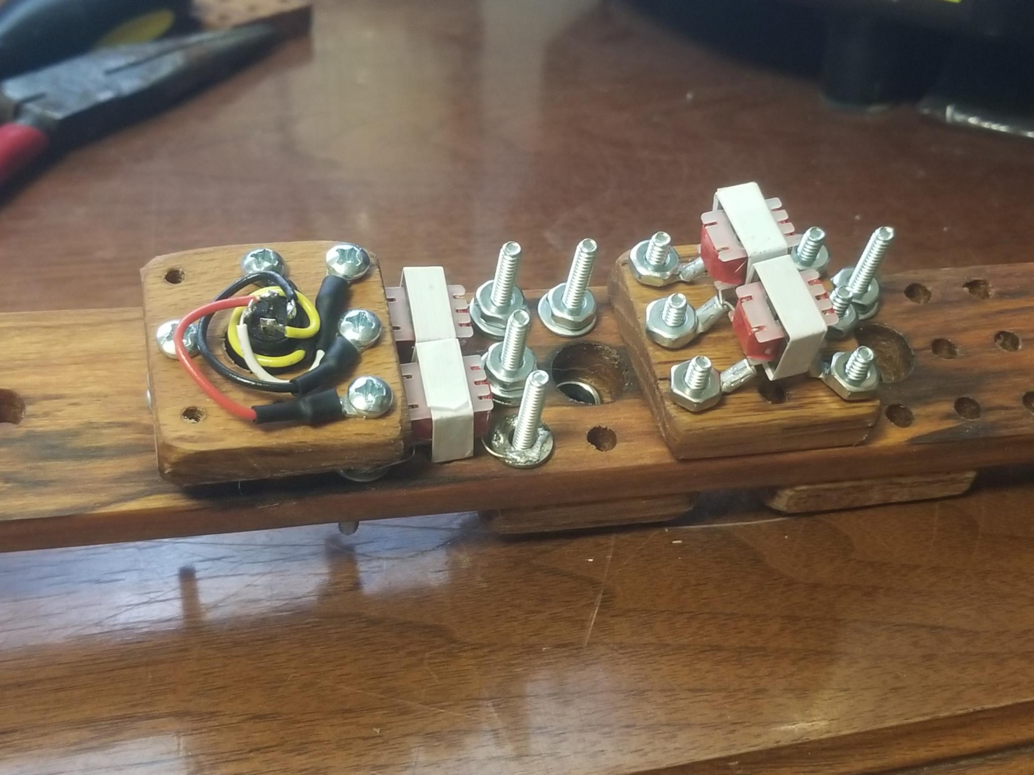
Crimpin' An' Sod'rin O' The 'Tronics
This part was a pain and took me three sit-down-and-crimp-and-solder sessions over 2 days. I eventually learned that it was more efficient to start by crimping and soldering the ring terminals onto the wires and then wrapping them up around the jack and soldering to its pins.
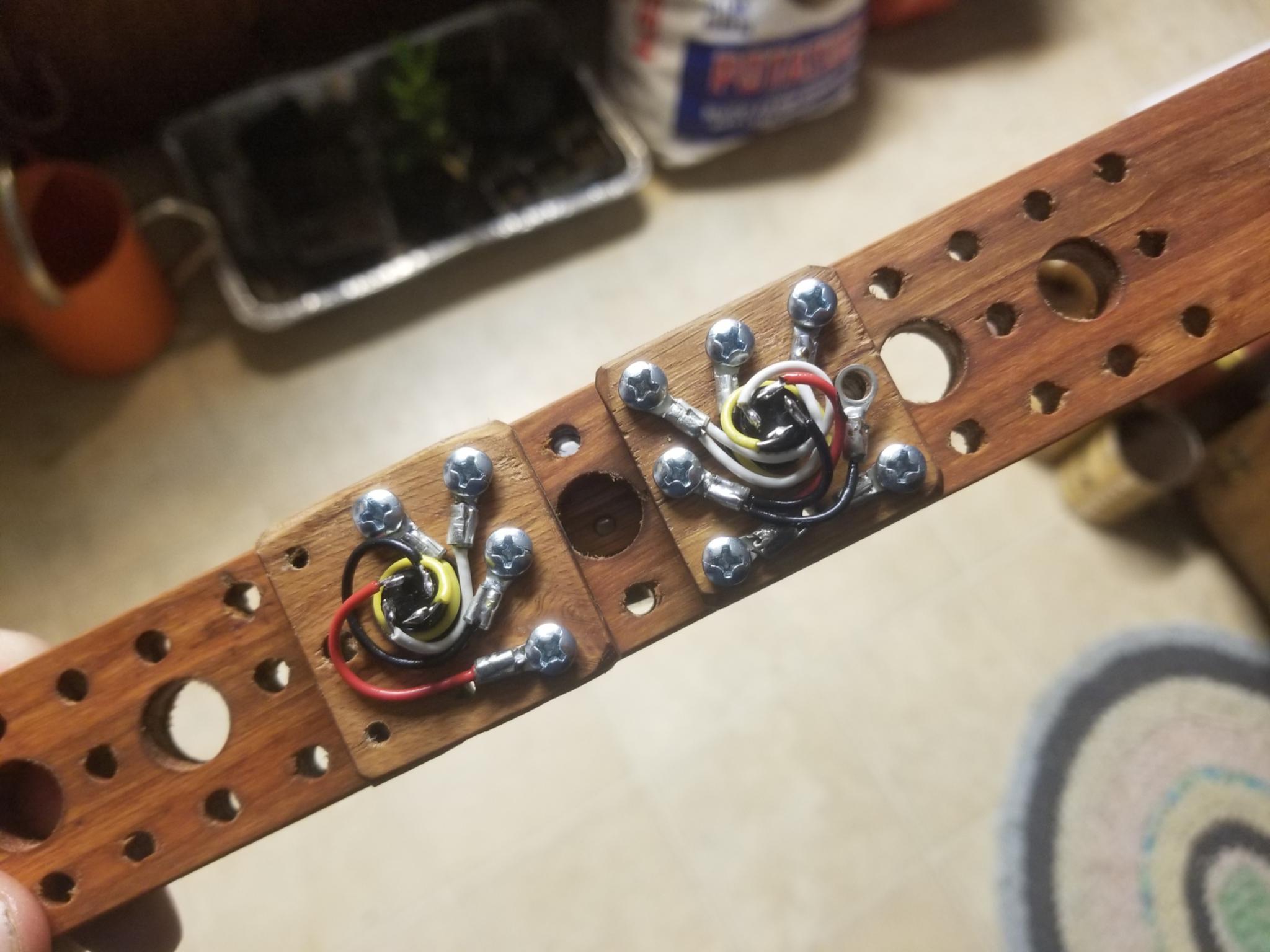
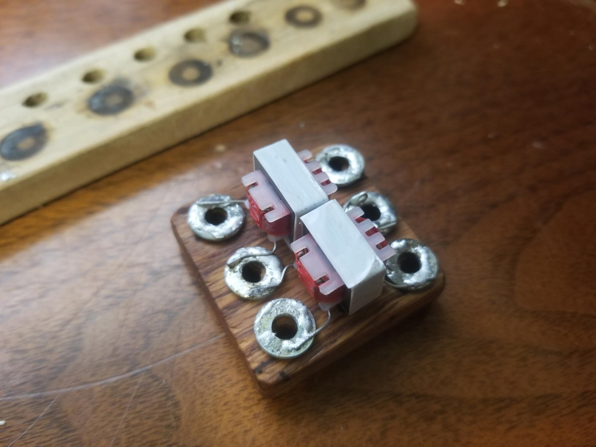
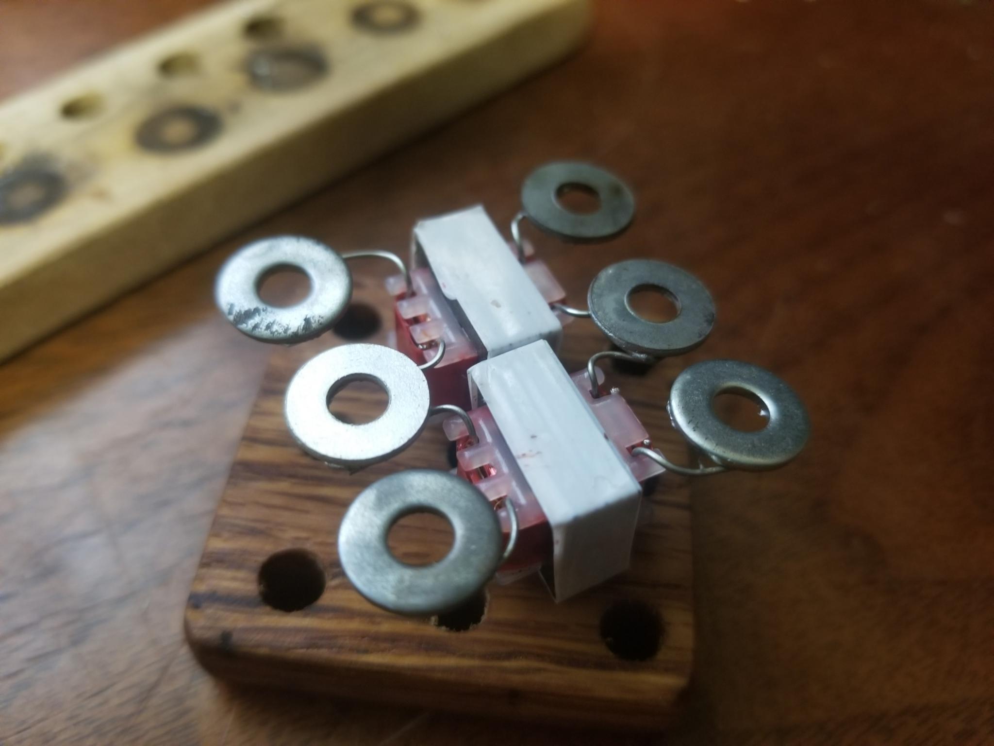
For the first of the two isolator panels that I made, I used the same ring terminals as on the wires on the jack panels, but I had to bend them to get them to fit into the space needed, and after making the third jack panel, I had run out of appropriately-sized ring terminals. So for the second isolator assembly I got some washers hot and managed to get some solder to flow onto them (I don't have flux), bent the isolators' legs in a nice way, and soldered them to the washers.
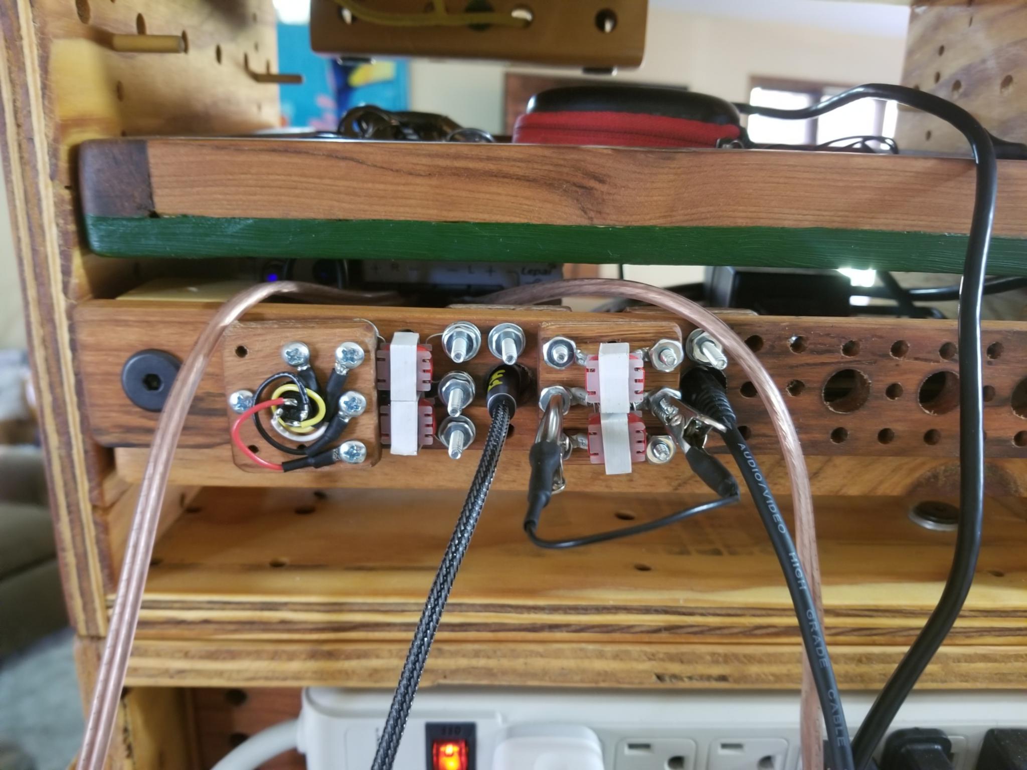
I decided I wanted one of the jacks to face backward so that this whole thing could be attached (via a couple of 1½″ cubes with threaded ¼-20 holes through them both ways) to the shelf that has my amplifier strapped to it, with the amp connecting straight to the back of the panel via a short cable.
I used up every last #6 nut that I had with me while assembling everything.
It all worked, but my FM transmitter refused to send a clean signal unless I connected its common ('ground') wire to something. So I made a short black wire with alligator clips (alligator clippability is part of the purpose of having all these screws sticking out) and connected the common screws across the transformers. Maybe connecting the grounds defeats the purpose of the transformers, but at that point I didn't want to reconfigure anything. Especially since I was all out of ring terminals.
Having put it all together and run out of nuts, and feeling the weight of all the hardware in it, I decided that I should keep some perfboard and 0.1″ headers around so that next time I want to build some extra-modular wiring thingamabob I can do it in a way that's more compact and doesn't use so many screws.
Maybe I could do it with wire wrapping somehow, hmmm.
Unrelated Software News
I finally ported NodeBuildUtil to Deno, creating TDBuilder.
And holy crap, it is so much more convenient than the old
bootstrapping process where node calls
npm to run tsc yaddah yaddah yaddah.
No need to clone a repo with all the boilerplate.
Just
import Builder from 'https://deno.land/x/tdbuilder@0.3.4/Builder.ts';
Deno is an enormous improvement over every other scripting language / runtime I've ever used. I love it.