A.k.a. WSPROJECT-200386
Renee needed a smart switch to control her old window AC unit. We didn't immediately find a ready-made thing that seemed suitable, so we built one.
Parts:
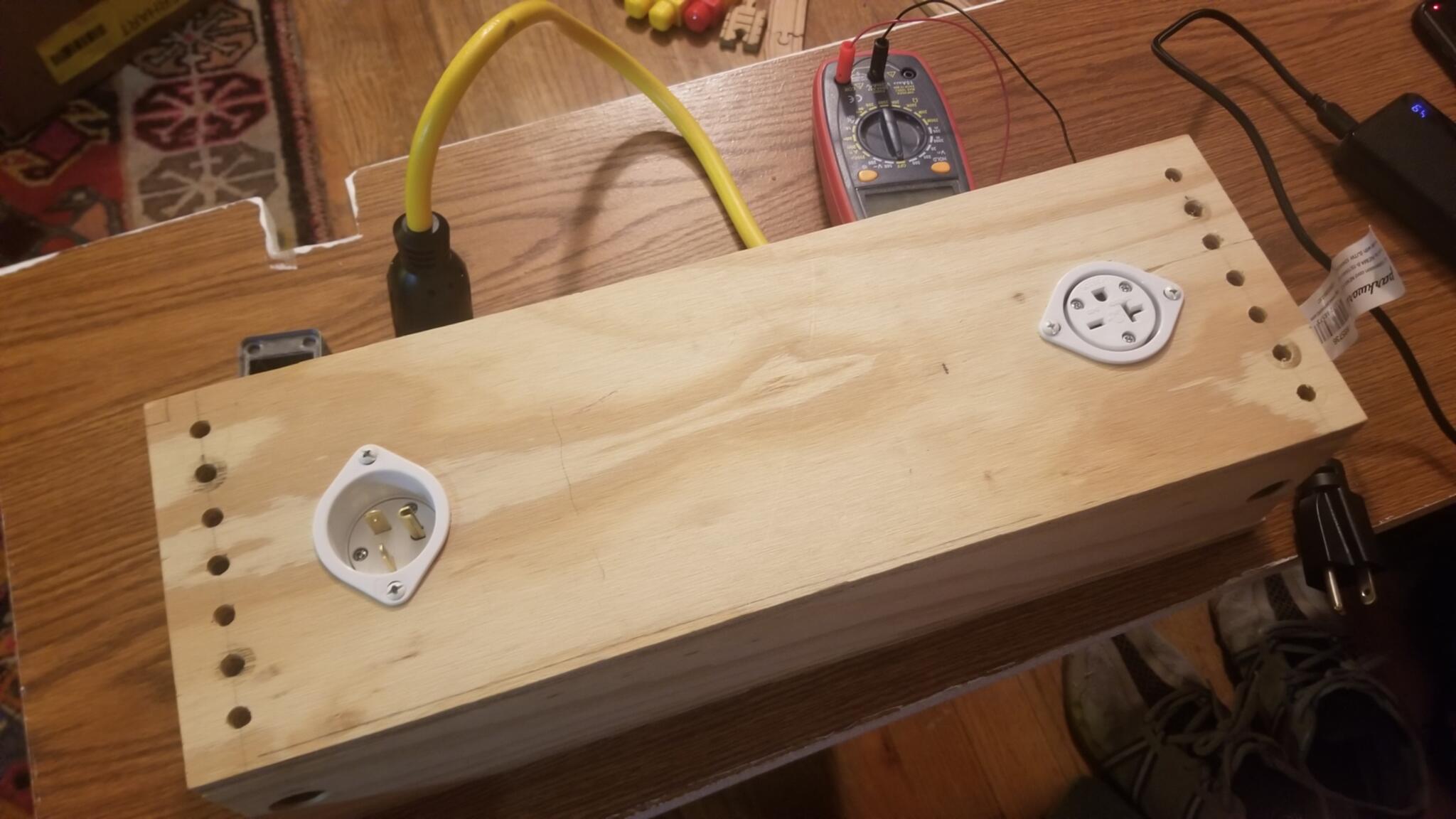
- NEMA 6-20P inlet
- NEMA 6-20P outlet
- 5V power supply
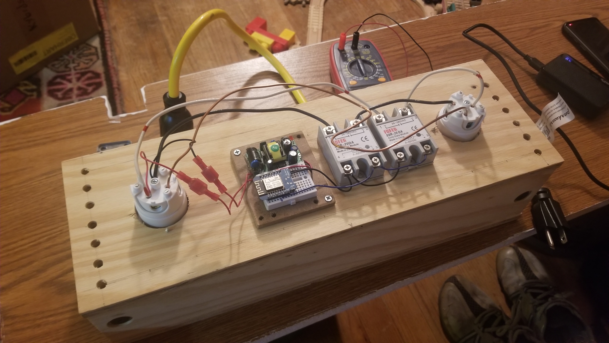
- WeMos D1 Mini
- Relay (two of them)
- Extension cord
- Two pairs of red 'quick disconnect' connectors, to connect the power supply's AC input to the inlet
- Random 12AWG solid wire I had lying around
- 1/4"-20 bolts and threaded inserts
- [Ply]wood scraps
- etc.
We installed Tasmota on the WeMos D1 Mini (a small, cheap, ESP8266 board of which I have many sitting in boxes in my workshop). It turns out that you can plug it into your USB port and then program it directly from tasmota.github.io using their 'web installer'. So easy, even Granny could do it!
My dad asked if those SSRs are designed for inductive loads.
The product page didn't say either way, so we're taking a bit of a risk, there.
This was before he realized we were switching AC power.
It being AC means that the voltage and the current should cross zero
120 times per second, and therefore we don't need to use special 'inductive load' relays.
We chose to make the box a hulking 18″x6″x4½″ so that we'd have plenty of room to lay out all the components, but also, being as wide as it is, it acts as a short bit of conduit for getting power from one point on the wall to another. This may or may not be useful, depending where Renee places it in her living room. For now it's just on the floor.
Rahter than using wire nuts or WAGO connectors to join the 240V wires between the inlet, outlet, and power supply, we soldered the leads to the power supply (18AWG) to the stripped ends of the 12AWG wires that connect the inlet to the relays.
The input wires are daisy-chaned across the two relays. This way we avoided any dangly wire junctions.
2023-07-05 Update
It does turn out that the SSRs that we bought get real hot while passing as much power as the air conditioner uses, and that there are perfectly suitable conventional relays that will do the job. Our plan is to replace one of our SSRs with a 2P2T conventional relay (maybe that one), and have the remaining SSR control it.
2023-07-09 Update
Modifications made yesterday:
- Replaced one SSR with that nice Siemens relay. It's intended to plug into some special socket, but we found that red quick-disconnect terminals attached nicely to the relay's tabs. The new relay has a 240VAC coil, which is controlled by the SSR's output.
- We added a 3-way on/off/auto switch. The switch is rectangular, so I 3D-printed a round flanged adapter so that we could just drill round holes in the plywood panel. The 3-way switch switches the + input of the SSR between disconnected, +3.3V from the WeMos D1 Mini ESP8266 board, and the same digital output as before.
I don't have any 240VAC appliances at my house. In order to test this thing, we rigged up an adapter cable from my dryer outlet (NEMA 10-30) with a NEMA 6-20 on the other end. NEMA 10-30s are deprecated due to not having a ground pin, only a neutral, and that neutral beomes the ground on the 6-20 end. The other way would be problematic, but I think this should be fine.
We also rigged up a couple of lightbulb sockets in series. I only had LED bulbs handy. When plugged into 240V they pulsate. I suspect that regular old incandescent bulbs would have behaved better. But the LED bulbs worked well enough to tell that power was on or not.
We were going to add some momentary buttons that Renee could program to do anything she wanted either through the Tasmota configuration on the ESP8266 or using Home Assistant, but we ran out of time.
We noticed that the relay hums when power is off due to, we eventually figured, the SSR being unable to switch fully off.
In the future, we may replace the SSR with a WeMos 5A 250V relay shield, which should solve the humming problem.
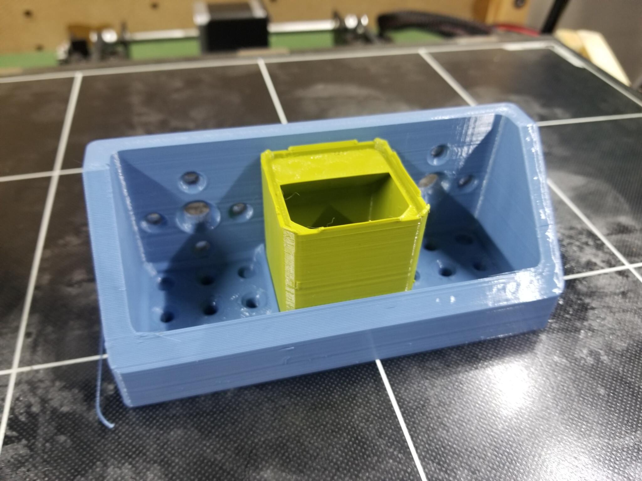
3D Printing News
I started printing some 'TOGridPile Bracket Shelves' for storing TOGridPile cups on a wall or a beam or something. The current designs have quarter inch walls around the outside, which makes the hull of the thing 'a funny dimension' (i.e. the box itself doesn't fit nicely on the 1½″ grid), but maybe that's okay, or maybe I'll come up with a way to make it work by combining with a TOGRack or something.